After a two-year hiatus, I’m back to post some more geeky camera stuff. This CLA (clean, lubricate, adjust) was completed in 2015 before other things in my life became higher priorities. Those things have gone away and I have finally have some time to finish this post.
A little bit about this lens
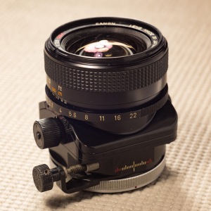
The Canon FD 35mm tilt shift lens is a fun lens to shoot with. While it suffers at the outer limits of its tilt and shift, it makes for a nice effect-lens. Canon has many tilt shift lenses in its EF mount, but not a 35mm.
This lens can be bought used between $250 and $700 depending on condition, who you buy it from, and how lucky you are. There are two versions. The earlier version has orange text for the metric distance marks and a more direct shift support arm. The later version has green text for the imperial distance marks, an offset shift support arm, and a smaller shift knob.
The shift support arm on the earlier version.
The shift support arm on the later version.
The shift support arm on the earlier version.
The shift support arm on the later version.
The offset shift support arm and the smaller knob on the later version help it avoid hitting the pentaprism box on Canon DSLR cameras.
The shift support arm on the earlier version hits the pentaprism on EOS cameras like this 5D mkIII.The shift support arm on the later version clears the pentaprism on EOS cameras like this 5D mkIII.
The CLA
The lower half
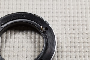
Some fungus among us.
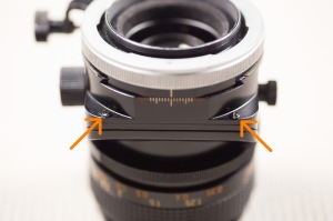
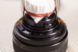
There are four screws that connect the lens to the shift section.
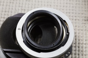
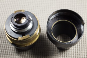
The shift section is removed.
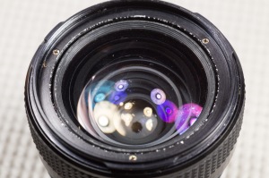
A view with the inside the lens.
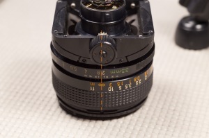
The large tilt knob lines up with the depth of field ring zero point.
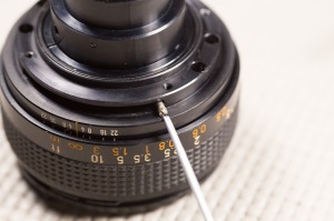
Be careful when moving the aperture ring as it is loose and the ball bearing detent might fly out.
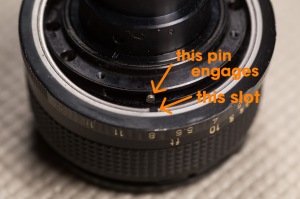
The aperture ring engages a pin attached to an armature. The armature transfers the movement of the aperture ring to the aperture housing.
The pin travels in the slot of the aperture armature ring.
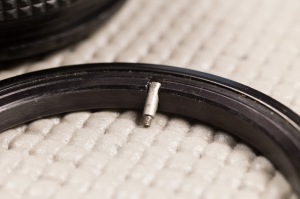
Removing the pin that connects to the aperture housing.
A view of the screw hole in the aperture housing.
Removing the pin that connects to the aperture armature ring.
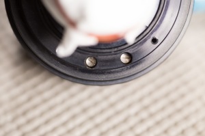
The screw on the left goes directly into the aperture housing. The screw on the right, which is slightly larger, connects to the aperture ring.
To make sure you have the correct screw. The larger one goes in the slot in the aperture ring.
The smaller screw is just a bit smaller than the slot. It is not the correct screw.
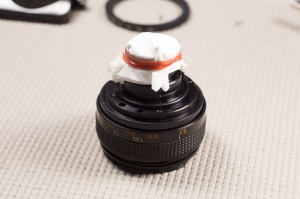
I’ve covered the end of the rear lens assembly to help prevent damage to the rear element.
Since we are getting ready to separate the focusing ring, helicoid, and lens assemblies we need to have a reference to make sure it gets put back together right. With the focus all the way to the infinity hard stop we can see that the helicoid, with the depth-of-field scale inscribed on it, lines up with the set screw (grub screw) in the lens structure. That’s not quite good enough because there are three set screws in the lens structure, so I’ll also point out the hole to the left.
There are two screws on each side of the rear lens assembly. They have very narrow slots in their heads, so you may have to file down the blade of your screwdriver. Don’t attempt to loosen these with a smaller screwdriver. You need one that is almost as wide as the head, otherwise you run the risk of damaging the head and possibly not be able to remove it.
With the screws removed we can see the holes were the helicoid mounts to the lens structure. We need another reference for how many turns of the lens structure it takes to free it from the helicoid. Counting turns might work, but it’s easy to miscount.
The distance from the edge of the focus ring to the bottom of the depth of field scale, at the closest focusing distance, is around 9.5 mm.
I had to Dremel the edges off of my spanner tool to fit the narrow slots on the spanner nut.
The spanner nut is removed.
The shift section and mount
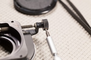
The set screws on the shift knob have a 1.5mm hex head.
If your lens has play in the shift knob you should start by looking at the space between the knob and the shoulder of the threaded shaft. On this lens the arm is slightly bent, which should be corrected before adjusting the spacing. The arm should be at a right angle to the shaft.
The arm is not square to the shaft. Ultimately, I reshaped the arm and repainted it.
Unfortunately, we’ll have to pry off the gross fake leather cover to reveal a screw.
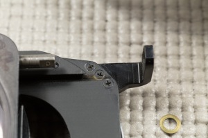
Here is one of three screws that holds the knob on. There are two set-screws on the side of the shift knob. This screw is very wide for having such a narrow slot. Please use a wide-bladed screwdriver to avoid marring or damaging the head. You might have to shave down the thickness of the blade for it to fit in the slot.
These three screws hold the arm. I’m removing the arm because it doesn’t meet the shift shaft at a right angle like it should. This causes uneven wear and more play in the shifting. Two screws came out with strong pressure, but the thrid would not. There was obviously some thread locker in use. With two removed I was able to move the arm and loosen the last screw. I ruined three phillips head bits doing it.
There’s a lot of little parts on the knob. From left to right: shift mount, washer, spring, set screws, knob, washer, screw, faux leather cover.
Removing the spanner nut releases the breech lock from the shift section. Be careful when removing the breech lock as there is a ball bearing beneath it.
The breech mount and shift section are separated.
The spring and ball bearing removed from their hole.
Remove the small screw and the silver ring unscrews from the black breech lock.
The optics
Unfortunately, this lens requires that you peel off the metal badge ring on the front of the lens to get into the optics. If you’re careful you can minimize the damage and it won’t be too noticeable. After the badge is off it’s a pretty easy lens to work on.
I need access to the lens from the front.
I used the clip off of a magnet tool to help pry off the name plate.
I used the clip from a magnet tool to help pry off the name plate. I wanted to reduce the amount of direct pressure on the ridged plastic part, but it still made impressions on it.
This photo shows the relationship of the name plate with the focus ring. The infinity mark lines up with the “35” text.
The name plate is quite thin and is glued onto the front of the lens. This is one of the worst designs I have seen as far as maintenance goes. The name plate did not come off easily and now is bent and has little dings and is bent.
Removing the name plate reveals three screws. Notice the silver marks on the metal from prying off the name plate. This makes me think that unless you have a definite problem in the front elements, don’t bother taking it apart.
These are some of the smallest screws in the lens.
Unscrew the three tiny screws and the plate comes off.
Unscrew the second set of three screws to release the focus ring from the body. Notice that the focus ring screw slots that allow fine positiong. Note the postion of the focus ring versus the scews. There should be impressions, but you can’t be sure.
With the three screws removed the focus ring detaches from the helicoid. Be sure to note the relationship of the focus ring to the helicoid, otherwise the markings will be off. Here, the 0.3 meter mark lines up with the three silver screws beneath it. There are impressions in the focus ring that tell me where the screws were tightened.
At last the helicoid is revealed. The plate with the three screws is what creates the hard stops on the focus. It has to be removed to unscrew the helicoid.
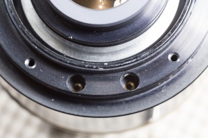
Removing the stop plate reveals more holes. Be sure to note which ones were used and approximately where the plate was mounted. Don’t unscrew the helicoid without understanding how it mates to the depth of field ring. Helicoids usually have multiple thread starting positions, meaning it can end up in a different rotated position when it reaches the end of its travel. The exact starting position must be determined as you unscrew it.
I’ve stopped unscrewing the helicoid just where it releases from the depth of field scale. I scribed a reference mark on the brass helicoid inline with the orange line to note where the orange line starts threading onto the helicoid.
The helicoid is separated from the depth of field ring. Be careful of the two brass guides in the rear lens assembly. They are now loose and can fall out. They are unique, so don’t get them mixed up. In fact, make a note of which one goes where.
Here I’m showing the two brass guides. The one on the left has a slot down the middle, while the other is solid. I’m using the small black pin in the middle to reference which brass piece goes on which side.
Double helicoid and opposite thread directions! The rear lens assembly, the black part, is also on a helicoid thread with the brass helicoid. Once again, note where the two pieces unscrew as there are many mounting points for helidoid threads. On mine the black pin lies between the second and third holes from the left on the bottom.
Using a fine point spanner tool I separate the front lens assembly from the helicoid. Be sure to support the bottom lens elements from the table. I used some Japan Hobby rubber tools to carefully hold the lens body without touching any elements.
The front lens asssembly holds two elements. There is a brass washer and a small positioning pin on the side. Unscrew the pin to remove the washer.
This spanner nut on the inside releases the secondary lens element from the front lens assembly.
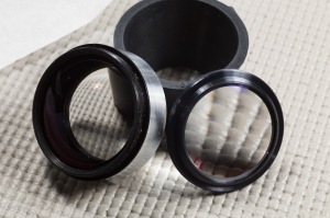
The front and secondary lens elements are separated.
Looking at the depth of field ring, use a small screwdriver to carefully remove the brass retaining ring that holds the aperture transfer mechanism.
The aperture transfer mechanism is now free from the depth of field ring. Clean and lubricate these parts.
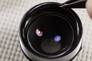
I’m planning on submerging the front metal lens assembly in my ultrasonic cleaner, so unscrewing this spanner nut will free the front lens element. Also, it allows me full access for removing the fungus. There was a thin plastic/mylar/nylon washer between the lens element and the spanner ring.
The front element sits next to its holder.
Screw the front and secondary lenses back together using the appropriate spanner nuts. Slip the large brass washer over the front lens assembly and attach the small positioning screw.
The slot in the rear lens assembly mates with the small screw in the fron lens assembly
Thread the rear lens assembly onto the helicoid, making note of where to begin the threading. Refer to an earlier photo where I mentioned this relationship. The screw in the front lens assembly will mate with the slot in the rear lens assembly (where the white grease is oozing out).
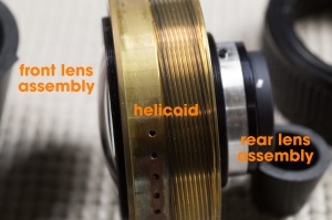
From left to right: the front lens assembly, helicoid, and rear lens assembly. By turning the rear lens assembly out of the helocoid you should notice that the front lens assembly does not move in or out, it only spins.
Screw the front spanner nut onto the helicoid to capture the front lens assembly.
Slide the small brass guides into the holes in the rear lens assembly. The guide with the slot cut in it is on the left. Which side it goes on may not be important.
Find your reference mark on the helicoid and thread on the depth of field ring.
With the depth of field ring screwed almost all the way onto the helicoid, the screw holes on the brass guides are visible.
The black spanner nut needs to be slightly loose to allow easy turning of the focus helicoid. That means using some thread locker (Loctite) between the brass helicoid and the black nut to prevent it from moving. I used the green thread locker, which allows for disassembly, but the red would also work and may be less runny than the green. Don’t use very much if you plan on ever unscrewing it again. It just needs to hold the nut from unscrewing, which doesn’t require much.
The focus ring is reattached. I made sure to line up the infinity mark with the focus line. You may want to wait on this step if you think you’ll need to adjust the infinity focus point. You’ll need to access the hard stop plate underneath the focus ring.
The last lens section is reattached with the sandwiched spanner nut.
Insert the aperture pins. The larger pin is on the right and connects to the aperture ring. The smaller pin on the left connect the aperture armature/transfer ring to the aperture housing. I had to use fine-point tweezers to hold them as I screwed. Be careful not to start them on an angle and ruin the thread. Turn the screw backwards until it feels like it clicks, then turn forward.
Unless you want a de-clicked aperture, install the spring and ball bearing now. Both parts are very small, so I had to use tweezers to place them.
It’s tricky to get the aperture ring on with the ball bearing in place. My ball bearing flew off once and landed on the floor. It’s so small you might not ever find it again. Mount the aperture ring against the ball bearing first and slide it down onto the aperture pin on the other side.
Wrapping Up
The re-assembly is basically doing this all backwards. You can group parts of it together and the exact order isn’t so important. I didn’t show all of the cosmetic repairs I made. For this lens I actually ended up sanding down the shift support arm so I could prime and paint it. Trying to bend it back to a right-angle proved too difficult to do without creating tool marks and paint damage. The end result looks good and you wouldn’t know it was repaired without foreknowledge.
The front plastic ring had some indentations from prying up the badge ring. I smoothed them out with some tools and then used acetone to remove scratches. I replaced the faux leather knob cover with some new faux leather. The front metal ring received some black paint to hide the scratches. Again, it looks pretty good and you wouldn’t be the wiser.
I painted on some flat black enamel paint and the front ring and now it looks great. It’s mostly underneath the name plate and won’t be seen much.Here’s a nice explosion of the parts.
I’m grateful for your work on the TS lens as I just bought one. It is slightly cloudy but most of the Australian technicians that I used to know have retired so, like you, I may have to build up my experience through known FD cheaper lenses. I have a few lenses with oily or stuck diaphragms (S, R, FL and early FD) so I have enough motivation as I have my own similar tools like yours. If you need information I have a set of original Canon books, manuals and brochures from the 1950’s until now. Regards,
I’m glad you found my blog helpful. The Canon 35 TS is fairly straightforward once you remove the badge ring. It’s a really fun lens to play with. Good luck and enjoy it!
Hi Gary. That’s great that you are able to do this kind of work. I’ve taken up video as a hobby and don’t do very much lens CLA anymore.
It would be neat to see the Canon books. My father has some old brochures and manuals that are nice to look at for reference. As far as lens repair, I’ve just relied on opening up a lens and kept track of how I took it apart.


Hello Mark,
I’m grateful for your work on the TS lens as I just bought one. It is slightly cloudy but most of the Australian technicians that I used to know have retired so, like you, I may have to build up my experience through known FD cheaper lenses. I have a few lenses with oily or stuck diaphragms (S, R, FL and early FD) so I have enough motivation as I have my own similar tools like yours. If you need information I have a set of original Canon books, manuals and brochures from the 1950’s until now. Regards,
Gary.
LikeLike
I’m glad you found my blog helpful. The Canon 35 TS is fairly straightforward once you remove the badge ring. It’s a really fun lens to play with. Good luck and enjoy it!
LikeLike
Hi Gary. That’s great that you are able to do this kind of work. I’ve taken up video as a hobby and don’t do very much lens CLA anymore.
It would be neat to see the Canon books. My father has some old brochures and manuals that are nice to look at for reference. As far as lens repair, I’ve just relied on opening up a lens and kept track of how I took it apart.
LikeLike